

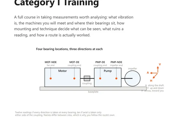
Vibration Analysis Training: Category I
A 60-page course book for the analyst who collects the data: units, sensors and mounting, the machines you will meet, and a route worked end to end.
Give one amplitude and the frequency it belongs to, and the calculator returns the same motion as acceleration, velocity and displacement, in six units and all three amplitude conventions. Acceleration, velocity and displacement are not three separate measurements of a machine. They are three descriptions of one motion, and at a single frequency each is one step of calculus away from the next.
A point vibrating at a single frequency traces a sine wave. Displacement is how far it moves, velocity is how fast it is moving, and acceleration is how quickly that speed is changing. Differentiating a sine multiplies its amplitude by the angular frequency, so with f in hertz:
That factor of 2πf is the entire conversion. Everything else is a change of unit.
The consequence is worth stating plainly, because it decides which sensor you fit. Dividing by 2πf twice makes displacement collapse as frequency rises, which is why a gear mesh at several kilohertz measures as a fraction of a micrometre while it destroys the gearbox. Multiplying by 2πf twice makes acceleration collapse as frequency falls, which is why a slow shaft with a serious unbalance barely registers in g. Neither quantity is wrong. Each one simply hides faults at the end of the range where its own factor works against it.
Two constants do all the remaining work.
| Conversion | Factor |
|---|---|
| g to m/s² | × 9.80665 (standard gravity) |
| in/s to mm/s | × 25.4 |
| mil to µm | × 25.4 |
| CPM to Hz | ÷ 60 |
The inch based units share the same 25.4 because a mil is a thousandth of an inch and a micrometre is a thousandth of a millimetre, so the ratio survives the change of prefix. Note that the mil is a unit of displacement and has nothing to do with the millimetre; confusing the two is a factor of 25.4 error in a clearance figure.
For a pure sine wave:
These follow from the shape of a sine and from nothing else. A real vibration signal is not a sine, and the ratio between its peak and its RMS is a measurement in its own right rather than a constant you can apply. When a single frequency component is being converted, as it is here, the sine relationships are exact enough to use.
Which convention to quote is a matter of trade practice rather than physics. Velocity is normally reported RMS, displacement peak to peak, and acceleration either RMS for a trended overall or peak for a time waveform. The important discipline is to say which one you used. A report that gives 4.5 mm/s without saying whether that is RMS or peak has left a factor of 1.41 for the reader to guess at, and readers guess wrong.
It converts one frequency component. It cannot convert an overall level.
An overall reading covering 10 to 1000 Hz contains components spread across that whole band, and each of them would have to be divided by a different 2πf. Picking one frequency to represent the lot produces a number that looks like an answer and is not one. If you need the overall in another quantity, integrate the spectrum, or set the instrument to measure the quantity you intend to report in the first place.
The same caution applies to converting a velocity spectrum’s overall into displacement in order to compare it with a proximity probe reading. The probe measures shaft motion relative to the housing; a seismic sensor on the housing measures something else. The arithmetic will complete, and the comparison will still be meaningless.
A velocity reading of 4.5 mm/s RMS at 25 Hz.
The angular frequency is 2π × 25 = 157.08 rad/s, and 4.5 mm/s is 0.0045 m/s.
Now hold the velocity at 4.5 mm/s RMS and move the frequency to 250 Hz. Acceleration becomes 0.7208 g RMS and displacement becomes 2.865 µm RMS: ten times larger in one and ten times smaller in the other, from a reading that has not changed. That is the whole argument for reporting machine condition in velocity, and the whole reason a displacement alarm is useless above a few hundred hertz.
Through the frequency of the component. Convert the velocity to metres per second, multiply by 2πf to get acceleration in m/s², then divide by 9.80665 to get g. At 25 Hz, 4.5 mm/s RMS works out as 0.0045 × 157.08 = 0.7069 m/s² RMS, which is 0.0721 g RMS. The same 4.5 mm/s at 250 Hz is ten times that in g, because the factor 2πf has grown by ten.
Because velocity is the rate of change of displacement and acceleration is the rate of change of velocity, and differentiating a sine wave multiplies its amplitude by the angular frequency 2πf. Without a frequency there is no factor to multiply or divide by. A reading of 4.5 mm/s is a different displacement and a different acceleration at every frequency it could have come from, so a converter that does not ask for one is guessing.
They are three ways of measuring the size of the same waveform. RMS is the root mean square, which relates to the energy in the signal. Peak is the largest excursion from zero, and peak to peak is the full swing from the lowest point to the highest. For a single sine wave, peak is RMS times the square root of two, and peak to peak is twice peak. For anything that is not a sine those relationships no longer hold.
No. An overall level is the sum of every component in a band, typically 10 to 1000 Hz, and each of those components would have to be divided by its own 2πf. There is no single frequency to use, so any answer produced by picking one is wrong by whatever margin the spectrum happens to allow. Integrate the spectrum instead, or set the instrument to measure the quantity that has to be reported.
Velocity, usually RMS, is the normal reporting quantity for machine condition because it stays reasonably flat across the frequency range where most faults live. Displacement, quoted peak to peak, suits low frequency work such as shaft motion and clearance. Acceleration suits high frequency work such as bearings and gears, reported RMS for a trended overall and peak for a time waveform.
The calculator gives you the number. These course books explain what the number means and how the measurement that produced it should be taken.
A 60-page course book for the analyst who collects the data: units, sensors and mounting, the machines you will meet, and a route worked end to end.
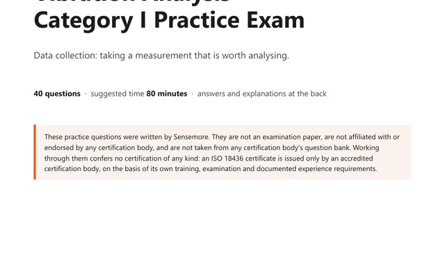
40 practice questions on taking a reading worth trending, from units and sensor mounting to what ruins a measurement, each answer worked rather than lettered.
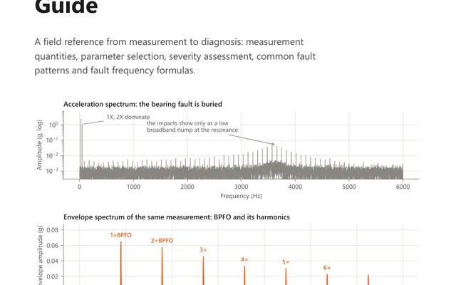
A 15-page field reference for the analyst on the route: measurement parameters, severity assessment, annotated fault spectra and bearing frequency formulas.