

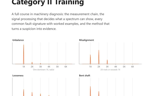
Vibration Analysis Training: Category II
An 88-page course book on vibration diagnosis: which fault produces which pattern, what phase adds, and how to disprove an answer before reporting it.
Enter the bearing’s geometry, its published frequency factors, or just the number of rolling elements, and the calculator gives you the four defect frequencies in hertz and in orders of running speed. The formulas underneath are the standard kinematic ones, which assume the rolling elements roll without sliding.
A rolling element bearing has four surfaces that can fail, and each produces impacts at its own rate.
| Frequency | Full name | What is damaged |
|---|---|---|
| BPFO | Ball pass frequency, outer race | The outer ring raceway |
| BPFI | Ball pass frequency, inner race | The inner ring raceway |
| BSF | Ball spin frequency | A rolling element |
| FTF | Fundamental train frequency | The cage |
None of them lands on a whole multiple of shaft speed. That is the single most useful thing about them: unbalance sits at exactly 1x, misalignment at 2x, and a loose foot at a neat integer series, so a strong peak at 3.58x running speed is almost certainly not any of those things.
With n rolling elements, a rolling element diameter d, a pitch diameter D, a contact angle φ and a shaft frequency fr in hertz:
The pitch diameter is measured centre to centre across the bearing, not across the bore or the outside. A common way to get it wrong is to use the bore diameter, which makes the ratio d/D far too large and pushes BPFO down towards the cage frequency.
Two relationships are worth carrying in your head. BPFO and BPFI always add up to n × fr, so if you have one you can get the other. And BPFO is exactly n × FTF, because the outer race sees every element pass once per cage revolution.
If the bearing designation is unreadable and the drawing is not to hand, count the rolling elements and use:
This works because (d/D) cos φ is close to 0.2 for the great majority of ball bearings, which makes the bracket in the formulas 0.8 and 1.2. Use it to decide where to put a cursor, not to write a report. The ball spin frequency depends on the ratio directly rather than on how close it is to 0.2, so it has no equivalent approximation and the calculator declines to invent one.
The formulas describe pure rolling. Real bearings slide as well, typically by one or two percent, and the amount they slide changes with load, clearance, temperature and lubrication. So the measured frequency drifts, and it drifts differently on a lightly loaded bearing than on a heavily loaded one.
The drift has a direction, and that is the part usually left out. Sliding means a rolling element travels a shorter angular distance per revolution than pure rolling would give it, so the measured rate comes out below the calculated one, not either side of it. A calculated 3.67 orders and a measured 3.61 are the same bearing, and that gap is 1.6 percent. A symmetric one percent window is both too tight to hold that and the wrong shape for a drift that only goes one way.
This is also how an alarm band is built. Start from the calculated order, take the lower edge down by about one percent for the slip and then a little further if the bearing is lightly loaded, leave the upper edge close to the calculated value, and add one bin either side for the leakage skirt. Then check what is next door: on a machine with looseness, a bearing band placed on the fundamental can reach down over the third harmonic of running speed, and using the second harmonic of the defect frequency instead buys the clearance. Define the band in orders rather than in hertz, so it follows the machine when the speed moves, and confirm a finding by its harmonic family rather than by one cursor position.
In an envelope spectrum. A spalled raceway produces a very short impact, and a short impact rings whatever structural resonance is nearby, typically somewhere in the kilohertz range. The energy involved is small; in a velocity spectrum dominated by 1x and 2x it does not show. Envelope processing bandpasses the signal around that resonance, rectifies it and takes the spectrum of the result, which throws the resonance away and keeps the rate at which the impacts repeat.
That repetition rate is the defect frequency, and in an envelope spectrum it shows up long before it appears anywhere else.
The band has to sit over that resonance, and it also has to sit below the sensor mounting’s own. Those two requirements can conflict, and the conflict is silent. A demodulation band of 2 to 5 kHz is a common preset, and it is also the standard trap: a two pole magnet has a mounted resonance around 2.5 kHz, which falls inside that band, so the top of the band is being measured through a mounting whose response has already collapsed. What comes back is the mounting rather than the machine. Take an ordinary acceleration spectrum out to several kilohertz first and look for the broadband hump, put the band over it and clear of the running speed region, use a stud or adhesive mount rather than a magnet where the band reaches into the kilohertz, and never a hand probe. On a very slow machine the impacts may be too weak to ring a high resonance at all, and then a lower band, a much longer record and a look at the time waveform are the way in.
A single peak at BPFO is weak evidence. A defect frequency with harmonics is strong evidence, because a genuine impact is not a sine wave and a series of impacts produces a series of harmonics. What the family looks like tells you roughly how far the fault has gone:
The last of those is the one that catches people out. A bearing whose defect frequencies have gone quiet is not a bearing that has healed.
A deep groove ball bearing with nine balls, a ball diameter of 7.94 mm and a pitch diameter of 39.04 mm, on a shaft turning at 1797 rpm.
The shaft frequency is 1797 / 60 = 29.95 Hz. The contact angle is zero, so (d/D) cos φ is 7.94 / 39.04 = 0.2034.
Note that BPFO and BPFI sum to 269.6 Hz, which is 9 × 29.95. That check costs nothing and catches a mistyped pitch diameter immediately.
They are the four frequencies a defect in a rolling element bearing generates. BPFO, the ball pass frequency of the outer race, is the rate at which rolling elements pass a point on the outer ring. BPFI is the same for the inner ring. BSF, the ball spin frequency, is the rate at which a rolling element turns about its own axis. FTF, the fundamental train frequency, is the rotational speed of the cage that holds the elements apart. None of them is a whole multiple of shaft speed, which is what makes them recognisable in a spectrum.
Approximately, yes. If the number of rolling elements is known, the outer race frequency is close to 0.4 times the element count times shaft speed, and the inner race frequency close to 0.6 times. The approximation holds because the ratio of rolling element diameter to pitch diameter is near 0.2 for most ball bearings. It is accurate enough to tell you where to look in a spectrum and not accurate enough to confirm what you found there. The ball spin frequency has no equivalent shortcut.
Because the formulas assume the rolling elements roll without sliding, and real bearings slide as well. The drift has a direction: the measured rate comes out slightly below the calculated one, commonly by one or two percent, so the match window is one-sided rather than symmetric. Allow roughly two percent below the calculated value and only a bin or so above it. A calculated 3.67 orders and a measured 3.61 are the same bearing, and insisting on an exact match is how a real finding gets argued away. Confirm it by the family it belongs to rather than by the single number.
The envelope spectrum, before the raw one. A bearing defect produces a short impact that excites a high frequency resonance, and the energy in that impact is tiny next to unbalance or misalignment at the low end of the spectrum. Envelope processing strips out the resonance and leaves the rate at which the impacts repeat, which is the defect frequency. In a raw velocity spectrum an early bearing fault is usually invisible.
They tell you which part of the bearing is moving through the load zone. An inner race defect turns with the shaft, so it passes in and out of the load zone once per revolution and the impact is amplitude modulated at shaft speed, producing sidebands spaced at one times running speed around BPFI. An outer race defect stays in one place and usually produces no sidebands. Sidebands around the ball spin frequency are spaced at cage frequency, because the element carrying the defect is being carried round by the cage.
The calculator gives you the number. These course books explain what the number means and how the measurement that produced it should be taken.
An 88-page course book on vibration diagnosis: which fault produces which pattern, what phase adds, and how to disprove an answer before reporting it.
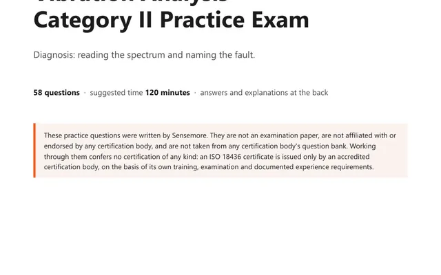
58 practice questions on vibration diagnosis, from fault signatures and phase to bearings, gears and resonance, each answer worked rather than lettered.
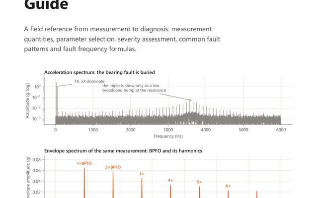
A 15-page field reference for the analyst on the route: measurement parameters, severity assessment, annotated fault spectra and bearing frequency formulas.