

Ultrasound Training: Category I
A 56-page course book on airborne and structure-borne ultrasound: decibels, directionality, the instrument's controls, leaks, steam traps and bearings.
Give the calculator a hole diameter and a line pressure, or a flow you have measured, and it returns the free air lost, the compressor power attributable to it, the energy that comes to over a year, and what that air is worth at your own tariff. The flow comes from choked orifice theory; everything after it is arithmetic on numbers from your own plant. The value of the air is kept separate from the reduction in the electricity bill, because they are different numbers and only the compressor’s control strategy joins them.
Above roughly 0.9 bar gauge, air leaving a hole reaches the speed of sound in the throat. Once the throat is sonic, nothing downstream can send information back upstream, so conditions on the outside stop mattering and the mass flow depends on the hole area and the absolute line pressure alone. That is what makes a leak table possible at all, and it is why a leak on a 7 bar line loses the same air in a quiet corner as in a draught.
The mass flow through the hole is:
mass flow (kg/s) = 0.61 × A × p_abs × 2.3612e-3
where A is the hole area in square metres and p_abs is the absolute line pressure in pascals, which is the gauge pressure plus 101325.
Two constants deserve naming. The 0.61 is the discharge coefficient: a sharp-edged orifice passes about 61 percent of what the frictionless equations predict, and it is that coefficient rather than the theory that makes these numbers agree with the tables the trade has printed for fifty years. The 2.3612e-3 is the choked mass flow constant for air at room temperature, worked out once from sqrt(γ / (R·T)) × (2/(γ+1))^((γ+1)/(2(γ−1))) with γ = 1.4, R = 287 J/(kg·K) and T = 293 K.
Converting mass to the volume a compressor has to make good, at a free air density of 1.204 kg/m³ at 20 degrees and one atmosphere:
free air (m³/min) = mass flow / 1.204 × 60
Below about 0.9 bar gauge the throat is not sonic, the choked formula overstates the flow, and a leak at that pressure should be measured rather than calculated.
Air itself is free. What costs money is the electricity used to compress it, and the bridge between the two is the compressor specific power, in kilowatts per cubic metre per minute:
Specific power is an input and not a constant buried in the code, because it dominates the answer more than anything else on the page and because it belongs to your machines rather than to the trade. It is the compressor house electricity meter divided by the discharge flow meter, and where both exist the whole business case takes one division. Where neither does, installing them is a better first project than a leak survey, because it makes every later claim checkable.
Note what that measurement already contains. Specific power is electricity in against air out, so the entire inefficiency of compression is inside it. There is no further multiplier to apply for the cost of compressed air against the cost of electricity, and applying one counts the same loss twice.
There is no published cost per leak on this page, and there should not be one anywhere. The cost depends on the specific power of that system, the tariff, the pressurised hours and the line pressure, and any of those can differ by a factor of two between two plants, so a borrowed figure can be out by a factor of four before anybody has measured anything. Use the plant’s own numbers and the only thing left to argue about is the size of the hole.
Hours matter as much as price, and they are usually underestimated. A leak does not stop when the shift does. It flows for as long as the header is up, so take the figure from the run-hour meters rather than from the production calendar.
The figure above is the value of the air the leak passes. Whether repairing the leak takes that money off the electricity bill is a different question, and it is answered in the compressor house rather than at the leak.
Every compressor turns a demand for air into a demand for electricity, and the slope of that relationship is set by how the machine is controlled:
On illustrative straight part-load lines chosen to separate those four cases, removing eight per cent of a machine’s capacity saves 2.4 per cent of its power under inlet modulation, 6.0 per cent under load and unload with ample storage, and 7.6 per cent under variable speed. The same repair, three different answers, or none at all. Those lines are not your machine: the real one is in the compressor’s performance data, or in a measurement of power at two flows, and finding out which line your plant is on takes an afternoon.
Report the two numbers separately. A leak report that quotes the value of the air as though it were a saving spends the rest of its life arguing about its own credibility, because the person reading it has the electricity bill in the other hand.
The largest input is the hole, and on a real leak the hole is inferred rather than measured. Flow follows the area, so the error in the diameter is squared on the way into the answer: a diameter 20 per cent low gives 0.64 of the flow and one 20 per cent high gives 1.44 of it.
That is why the calculator rounds everything to two significant figures and prints a range at plus or minus thirty per cent beside the central figure. A leak cost quoted to three significant figures is not credible when nobody has measured the orifice, and stating the spread yourself is far better than having somebody discover it in a review.
State the six assumptions every time the number is used: the estimated diameter, the line pressure, the hours the system is pressurised, the specific power, the tariff, and the control strategy the saving depends on. Then give the range and say which end you would defend.
A 3 mm hole at a cracked fitting on a 7 bar gauge header, in a plant whose system is pressurised 8000 hours a year behind compressors metered at 6.5 kW per m³/min.
The hole area is π × (0.0015)², which is 7.069e-6 m². The absolute pressure is 801325 Pa. The mass flow is 0.61 × 7.069e-6 × 801325 × 2.3612e-3, which comes to 8.16e-3 kg/s. Dividing by 1.204 and multiplying by 60 gives 0.41 m³/min of free air, about 410 litres per minute, or 14 CFM.
That air takes 0.41 × 6.5 = 2.6 kW of compressor power, drawn for as long as the header is up. Over 8000 hours it is 21 000 kWh a year, and multiplying by your own tariff gives the value of the air.
Carry the uncertainty with it. At plus or minus thirty per cent the same leak is somewhere between 15 000 and 27 000 kWh a year, and the diameter estimate accounts for nearly all of that spread.
Then apply the control strategy before promising anybody a saving. Under variable speed those 21 000 kWh are worth about 20 000 kWh off the bill; under inlet modulation about 6 300; behind a fixed-speed machine held at full load by a sequencer, nothing at all until enough leaks are repaired to switch a machine off.
The same flow arithmetic at other hole sizes, all on a 7 bar line:
| Hole | Free air | Attributable power | |
|---|---|---|---|
| 0.5 mm | 11 L/min | 0.40 CFM | 0.073 kW |
| 1 mm | 45 L/min | 1.6 CFM | 0.29 kW |
| 2 mm | 180 L/min | 6.4 CFM | 1.2 kW |
| 3 mm | 410 L/min | 14 CFM | 2.6 kW |
Flow follows the area of the hole, not its diameter, so doubling the diameter quadruples the loss. That is worth remembering when a leak is described as small, and it is also why a repair list is worked in size order: a few of the largest leaks carry most of the total, and the same afternoon spent on the smallest ones changes the compressor house by less than its own measurement noise.
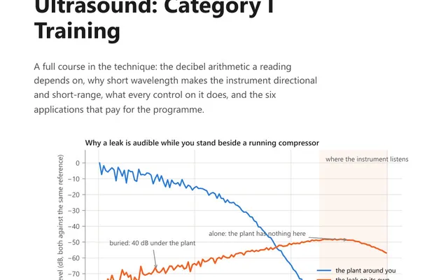
A leak radiates broadband ultrasound as the escaping flow turns turbulent, and instruments listen around 40 kHz because the wavelength up there is short. Short waves are directional: the sound casts a shadow, so the instrument can be pointed at the leak rather than merely hearing that one exists somewhere.
The noise of a working plant lives at wavelengths measured in metres and goes around obstacles instead of casting shadows. That separation is what lets a leak survey happen during production rather than during a shutdown, and it is why the survey and the cost calculation belong together: one finds the holes, the other decides which of them gets fixed first.
About 45 litres of free air per minute on a 7 bar gauge line, roughly 1.6 cubic feet per minute. It comes from choked orifice theory with a discharge coefficient of 0.61, the coefficient that reproduces the leak tables the trade has published for decades. Loss scales with the area of the hole, so a 2 mm hole loses four times as much and a 3 mm hole nine times as much. That squaring cuts both ways: a real leak's effective diameter is inferred rather than measured, so a 20 percent error in it is more than a factor of two in the answer, and the result belongs in a range of plus or minus thirty percent.
Because above roughly 0.9 bar gauge the air reaches the speed of sound in the throat of the hole and the flow chokes. Once the throat is sonic, conditions downstream can no longer influence what passes through it, so the mass flow becomes a function of the hole area and the absolute line pressure alone. That is the reason a single leak table can be printed and used anywhere. Below that pressure the flow is no longer choked and has to be measured rather than computed.
It is the electrical power a compressor draws to deliver a given volume of free air, expressed in kilowatts per cubic metre per minute. A screw compressor at 7 bar is commonly 6 to 7. It is the number that converts lost air into lost electricity, so it sets the whole answer: two plants losing identical air through identical holes pay different amounts if their compressors differ. Take it from the compressor house electricity meter divided by the discharge flow meter, or from the machine data sheet. Because it is measured electricity in against air out, it already contains the entire inefficiency of compression, so no further multiplier belongs on top of it.
With airborne ultrasound. Air escaping a hole turns turbulent as it leaves and radiates broadband sound well above hearing, and instruments listen around 40 kHz because the wavelength there is short enough that the sound is directional and casts a shadow. Machinery noise in a working plant lives at wavelengths measured in metres and bends around obstacles instead, so a leak stays detectable and locatable during production rather than only during a shutdown.
Usually, because it flows every hour the header is pressurised, including nights and weekends. Whether it is worth repairing is a calculation on your own numbers, with two halves that must not be added together. The first is the value of the air the leak passes: its flow times your specific power times your tariff. The second is the reduction in the electricity bill, which is that figure multiplied by however much of a flow reduction your compressor control turns into a power reduction. Under variable speed nearly all of it; under inlet modulation a small fraction; behind a fixed-speed machine held at full load by a sequencer, none until enough leaks are fixed to switch a machine off.
The calculator gives you the number. These course books explain what the number means and how the measurement that produced it should be taken.
A 56-page course book on airborne and structure-borne ultrasound: decibels, directionality, the instrument's controls, leaks, steam traps and bearings.
A 51-page course book on analysing the ultrasound signal: bearing condition, acoustic lubrication as a procedure, valve leakage and steam trap tests.

43 practice questions on airborne and structure-borne ultrasound, from decibels and heterodyning to leaks and bearings, each answer worked in full.